Company Insight
Communicating safety
Ports and the shipping industry should be aware, that when fenders fail or do not work properly due to incorrect designs or a wrong safety factor, the risk of accidents during the berthing process and the resulting costs to the port in terms of repair and downtime are tremendous. These risks are by no means worth saving on safety.


SPC Cone Fender System | Ferry Terminal | Sweden
The primary purpose of marine fender systems is to enable vessels to safely berth against a structure under a predicted set of operational conditions, without any damage to the structure, the vessel, or the people working aboard and ashore.
The overall philosophy is simple: the fender’s capacity to absorb the energy of a vessel should be greater than the energy required to bring the vessel to a complete halt during berthing. The engineering around fender designs has been described as “part science – part art” in that it requires comprehensive experience to fully understand how to provide a good balance between performance, functionality and cost.
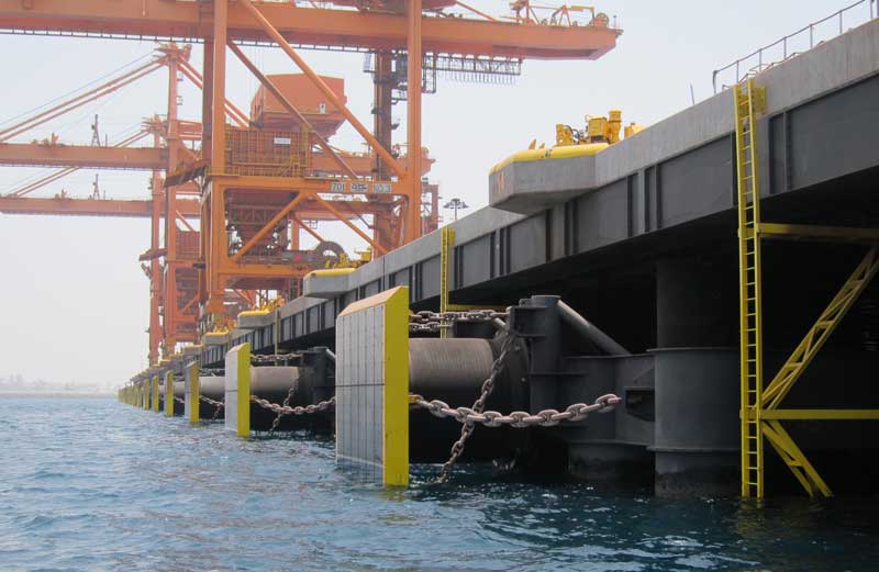
CSS Cell Fender System | Bulk & Aggregate Jetty | Oman
The question is how can ports ensure to provide safe operations for the shipping industry? The safest option is consult with at least one experienced and successful fender manufacturer. Nevertheless it is a great advantage for ports to have a basic understanding of berthing processes oneself. Being one of the leading fender specialists, ShibataFenderTeam sees it as their responsibility to pass their extensive knowledge and experience on, to not only design engineers but as well to end users. By focusing on the science and engineering aspects, creating awareness and understanding for safety critical products, is an important concern for ShibataFenderTeam.
Therefore, we would like to emphasize the basic fendering concept in simple steps below:
Step 1 – Stop the vessel
Berthing Energy is a function of kinetic energy, which we derive through the formula E = ½ m * v2. During the design of berths, which happens long before the fender selection, it is important to know the details of all of the vessels that will, or in the future be using the berth. The mass or displacement tonnage of the vessel is the mass used to determine the Normal Berthing Energy (EN) and as you would expect, the larger the mass, the larger the berthing energy, under the assumption of the same speed.
Secondly, the berthing velocity needs to be estimated for each vessel. This will depend on variables such as the location of the structure, environmental and navigational conditions and whether the vessel will be tug assisted or not.
Once all of the data has been obtained, the Normal Berthing Energy (EN) for each vessel can be calculated.
Step 2 – On the safe side
A Factor of Safety (FOS) is applied to the Normal Berthing Energy such that the fender system will be capable of absorbing reasonable abnormal impacts, which may be caused by mishandling, malfunction, adverse wind and current or a combination of all.
Consideration in selection of an appropriate Factor of Safety should be given to:
- Consequence of failure (high cost / lost revenue)
- Frequency of use of berth / design life
- Load sensitive structures
- Range of vessels using the berth
- Hazardous cargoes (environmental damage)
Once the appropriate Factor of Safety has been determined, the Abnormal Energy (EA) can be established which is calculated by EA = EN x FOS .
It is important to know, however, that calculation of Normal and Abnormal Berthing Energy is based on experience, while the actual berthing energy can vary substantially each time the vessel berths.
The calculation of the berthing energy should be done by skilled and certified engineers, as it is their expertise that can make the difference between safety and failure.
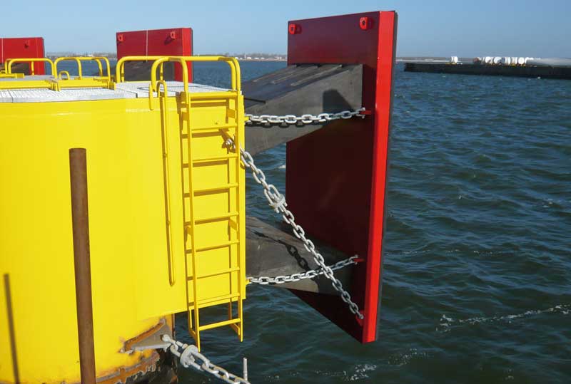
FE Element Fender System | Ferry & RoRo Terminal | Germany
Step 3 – Engineering excellence
Once the Abnormal Energy has been calculated, designers can look at suitable fender systems. The best calculations and safety factors, however, have limited impact when the chosen fender supplier lacks experience, resulting in incorrect designs and an increased risk of accidents.
Creating and protecting values is the principle at ShibataFenderTeam. Engineering excellence of a safety critical fender system means to furthermore take into account the following aspects:
- Energy Capacity
- Height requirements (which can be minimum or maximum)
- Reaction Force limitations of the structure
The strict compliance with industry guidelines for the design of fender systems and the respective testing procedures of samples and finished products, is another factor which accounts for a credible and reliable manufacturer. This alone, however, does not guarantee the performance of the final product.
To ensure safety in berthing operations, ports and the shipping industry should rely on:
- Excellent design of fender systems by certified, experienced professionals
- Experienced manufacturer exceeding industry standards
- Extensive proven track record of the supplier
The entire process is summarized in the graph below, where the probability of exceedance (ie the chance that the vessel will exceed the capacity of the fender) is minimized.
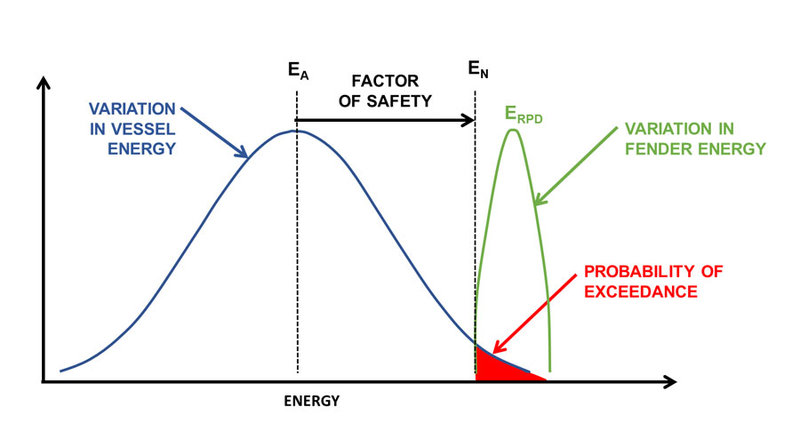
Engineering to ensure a safe environment for ports and the shipping industry
POOR PLANNING AND OVERCONFIDENCE: THE MAIB’S MAIN FINDINGS
If there is one takeaway point from the inquiry it is that poor planning was at play.
Investigators discovered the lead pilot had not informed the bridge team of his plan for the turn around Bramble Bank. There was an “absence of a shared understanding of the pilot’s intentions for passing other vessels or for making the critical turns during the passage”.
Elsewhere, the master and port pilots were blamed for “complacency and a degree of over-confidence”.

There was an “absence of a shared understanding of the pilot’s intentions”
CMA CGM, which took delivery of the Vasco de Gama in July 2015, has acknowledged MAIB’s findings, and claims to be addressing the aforementioned issues raised in the report.
“Following this grounding, CMA CGM and ABP [Associated British Ports] Southampton have been working together,” said a spokesperson for the company in an email.
“As mentioned in the MAIB official report, CMA CGM has already taken measures to prevent this type of incident to happen again. CMA CGM is strongly committed to ensuring the safety of its operations and its crews in accordance with local and international regulations.”
All straight-bat stuff. ABP could not be reached for comment.

Unavoidable inquiry: why the MAIB inquiry needed to happen
Simon Boxall, a maritime expert from the University of Southampton, believes MAIB’s findings to be fair, despite Bramble Bank’s reputation as “a navigation hazard” due to it susceptibility to “slight movement after major storms”.
“Looking through the report there was no evidence of unforeseen mechanical failure on the ship, nor of abnormal weather conditions,” he says.
“On that basis, the two pilots and the ship’s master should have been in a position to safely navigate the vessel into port. It would appear to be user error – which is what the report says in so many words.
Introducing ways of reducing user error can only be seen as a good move

“In light of this, introducing ways of reducing user error can only be seen as a good move.”
Boxall also acknowledges things could have been a lot worse. As the Vasco de Gama was re-floated relatively quickly, the port didn’t suffer any kind of blockage – which, given the vessel’s size, would have brought Southampton to “a standstill”.
Neither did the vessel endure any serious damage. Nonetheless, an investigation was still necessary.
“If reports such as this are not produced then the safe navigation of shipping is not improved,” says Boxall.
“In the same way an airline near-miss is thoroughly investigated, it is important that the same is done for shipping – not as a witch hunt, but as a fact finding investigation to improve safety.”
Svein Kleven is senior vice president of engineering and technology for Rolls-Royce. Image courtesy of Rolls-Royce
Contact us
ShibataFenderTeam
Tarpen 40, Haus 1b
22419 Hamburg, Germany
Tel. +49 (0)40 63 86 10 - 170
Fax +49 (0)40 63 86 10 - 180
E-mail: info@shibata-fender.team
Website: www.shibata-fender.team


